Unfortunately, the Spartan-3E you are using has only 350 kbits of block RAM, not 8 Mbits like you require.

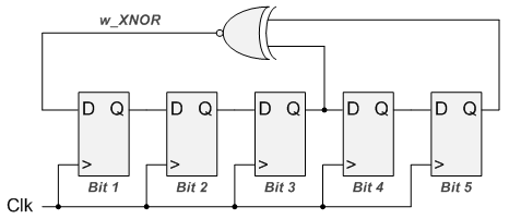
If you use Xilinx ISE, there is probably also a "wizard" to generate the RAM block and set up the initial contents for you. Read the Spartan-3 Generation User's Guide (Chapter 4) to see how to instantiate the RAM and how to access the data from the RAM. Use a synthesis directive in your HDL code or UCF file to specify the initial contents of the RAM. To do this you instantiate a block RAM, but don't connect to the write pins. Method 1: Create ROMs in your FPGA designīecause you have the same data in every board, one option is to use block RAMs in the FPGA, configured as ROM. LFSRs can also be used to implement a counter efficiently if you don't care about the intervening states, just how long takes to count down to some terminal value. Essentially, a single look-up table in a single logic block can be used to implement up to 32 registers worth of shift register (depending on architecture). Xilinx app note XAPP052 gives a handy table of connections to be used to generate any size PRBS from 3 to 168 registers.Īpp note XAPP211 shows how to implement them efficiently in Xilinx devices. Notice that it is not always the final two registers that are "tapped" to generate the incoming bit of the shift register. In communications testing, longer sequences are more common, mainly to exercise more of the low frequency behavior of the system: This can be important if you are using the PRBS to test a system with ac-coupling.longer runs will stress the system more. If you need the all-0's state not to lock up, you can use an XNOR in place of the XOR gate, and get a sequence that includes the all-0's state and locks up in the all-1's state.Īlso be aware that the longest run of 1's produced by this state machine is 5 in a row, and the longest run of 0's is 4 in a row.

This means you have to be sure (using a synthesis directive in the Verilog or constraints file) that the registers don't initialize to the all-0's state.

The all-0's state is a lock-up state - if the state machine gets into that state by an error, it will be stuck permanently in the all-0's state, as you can see because 0 ^ 0 = 0. Of all the states that can be encoded by 5 registers, only one is not used, which is the all-0's state. The state machine traverses 31 states ( \$2^n-1\$, where n is the number of registers) before repeating itself. This is, as others mentioned, a linear feedback shift register, or LFSR, and it generates the maximal length pseudo-random bit sequence that can be produced with a 5-bit state machine. This is easily rendered in Verilog as reg d

You probably do want something like the circuit shown by clabacchio.


 0 kommentar(er)
